Introduction. Corrosion of reinforcing steel in concrete structures is a serious problem from the perspective of both safety and economy and affects directly the sustainability and life-time of the infrastructure. Reinforced concrete has been in widespread use in a variety of civil engineering constructions for a long time. Problems related to its durability and maintenance are of considerable importance because of the enormous scale of its usage and demanded long service-time. Corrosion of reinforcing steel is one of the most common degradative processes which can affect reinforced concrete structures causing their loss of serviceability, needs for repairs, premature pulling down, and in extreme cases, leading to structural collapse. Many factors affect the rate of corrosion reactions inside the concrete such as type of cement and concrete composition, temperature, humidity, concrete resistivity, pH, carbonation, chlorides, oxygen, and other corrosive species and gases.
Mathematical model. Current density is usually a complex function of system geometry, properties of the electrode surfaces, and the material composition of the electrolyte. An overall electrode process consists of several consecutive steps: i) transport of electroactive species between the bulk of electrolyte phase and electrode surface, ii) interfacial charge transfer, iii) solvation reactions, iv) electrocrystalization, and v) homogeneous chemical reactions with rates independent on the electrode potential. Interfacial charge transfer step is of fundamental importance which rate is directly related to the potential difference across the double layer. In macroscopic description this potential difference is related to the current density by the proper polarization curves. We do not assume a priori, where the anodic or cathodic zones are, so the general Butler-Volmer kinetics has to be used.
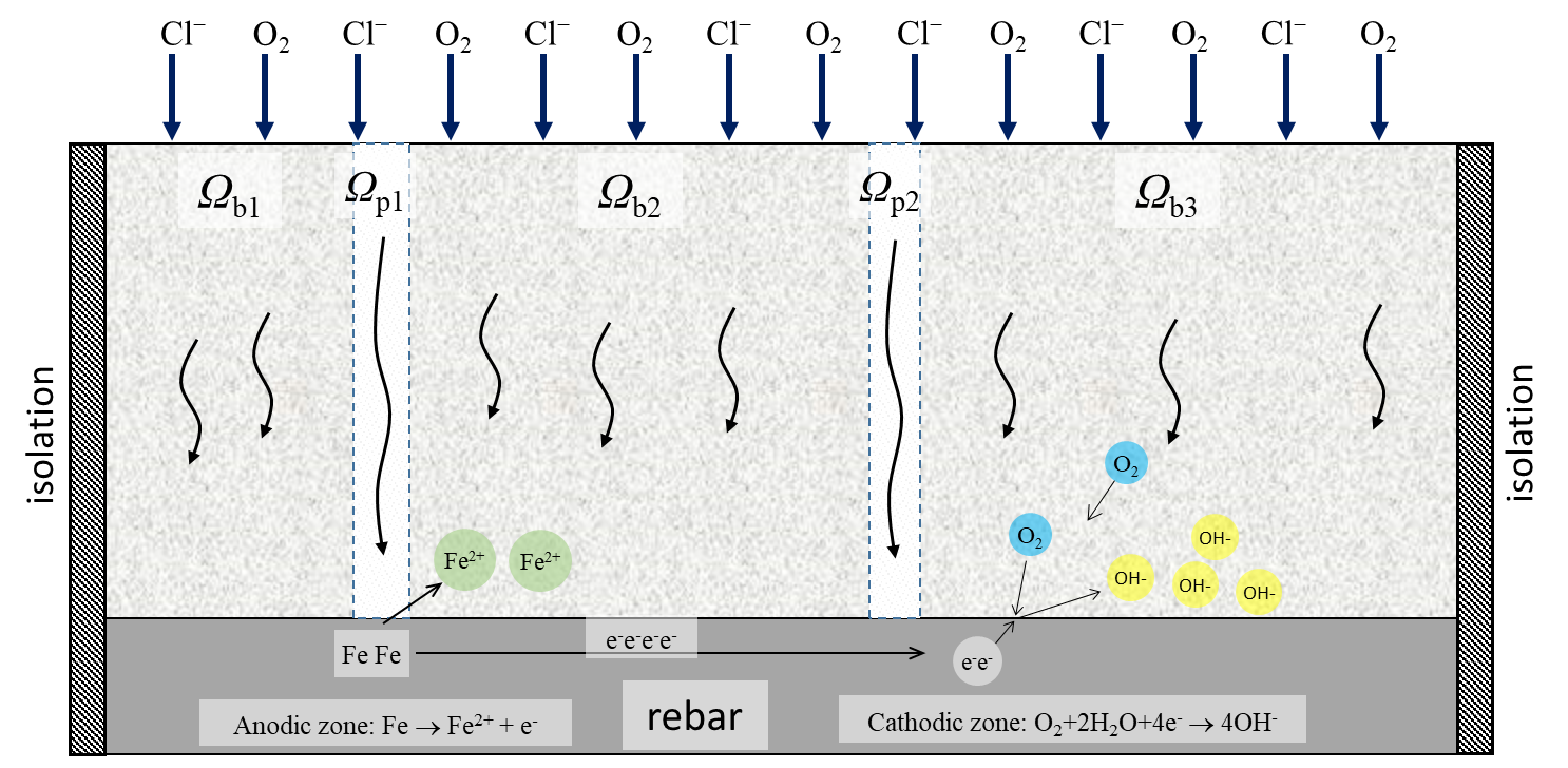
In the model we describe the corrosion of rebars covered by water saturated concrete with cracks in 2D geometry (at a cross-section perpendicular to concrete surface along the rebar). The cover of the concrete is in contact with oxygen and chlorides which can penetrate concrete and cracks with different rate – Fig. 1.
Fig. 1. 2D schematic graph representing main corrosion reaction in concrete. Anodic and cathodic zones result from the solution of the model. In the presented picture the anode areas tend to grow in the area adjacent to the pore mouths due to quicker supply of chloride ions.
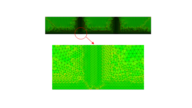
Numerical method. Rebar corrosion model was solved by finite element method (FEM) using second order Lagrange base functions. Fig. 2 shows the mesh, which was used in the calculations of rebar corrosion in cracked concrete.
Fig. 2. Mesh used in calculations of rebar corrosion in cracked concrete (top) and magnified part of the mesh in a crack area (bottom).
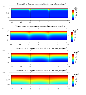
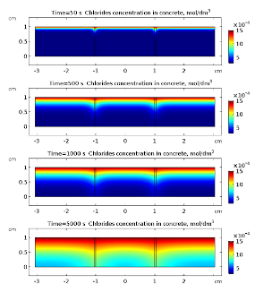
Applications. In Fig. 3 and 4 oxygen and chloride concentrations in cracked concrete are presented for selected times. Both oxygen and chlorides diffuse into the concrete. This transport is much faster in cracks what is clearly visible in Fig. 3 and 4.
Fig.3. Oxygen concentrations in a cracked concrete for selected times t = 50, 500, 1000, 5000 s.
Fig. 4. Chloride ions concentrations in a cracked concrete for selected times t = 50, 500, 1000, 5000 s.
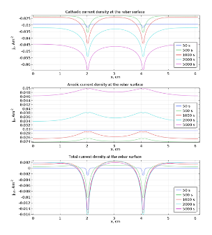
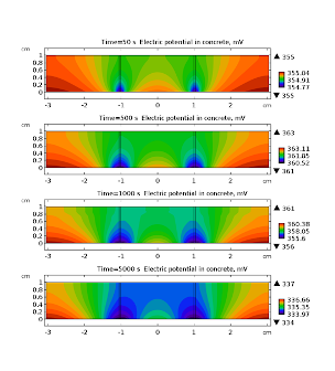
Once the chloride reach the surface of rebar and its concentration rises above threshold value (~18.2 g·m-3) the passive film on the iron is broken and the corrosion reactions and may start. Anodic dissolution of iron is coupled with cathodic reduction of oxygen . The kinetics of the later reaction is governed by the presence of oxygen near the surface of rebar, hence its rate is time dependent due to variable concentration of oxygen. This is clearly visible in Fig. 5 where cathodic current density is displayed for selected times. The overall density current does not change monotonically with time (Fig. 5). It is related to the fact that cathodic current density is decreasing while anodic is increasing. This simulation shows that dynamic behavior of corroding steel may exhibit complicated pattern. In Fig. 6 electric potential distributions over the concrete are presented. It is almost constant in space (relative variation does not exceed 1 %) because the conductivity of the saturated concrete is relatively high. Nevertheless, its average value varies with time appreciably.
Fig. 5. Cathodic, anodic, and total current densities at the rebar surface for selected times t = 50, 500, 1000, 2000, 5000 s.
Fig. 6. Electric potential in a cracked concrete for selected times t = 50, 500, 1000, 5000 s.
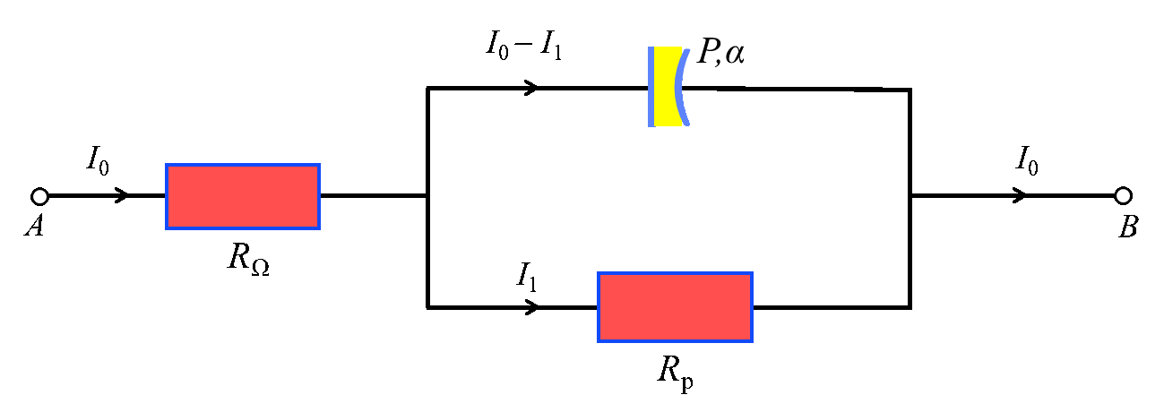
Transient respond analysis of rebar in concrete. In galvanostatic pulse (GP) method a constant current is applied and the resulting transient voltage is measured. In the standard approach for description of galvanostatic pulse response by the equivalent circuit RW-(RpCdl) has a double-layer capacitance modeled by a capacitor with capacitance Cdl. But the corrosion layer at the interface steel/concrete is usually not solid and homogeneous, so the constant phase element CPE(P,a) seems to be more accurate – Fig. 7.
Fig. 7. An extended Randles circuit used for modeling concrete/rebar interface.
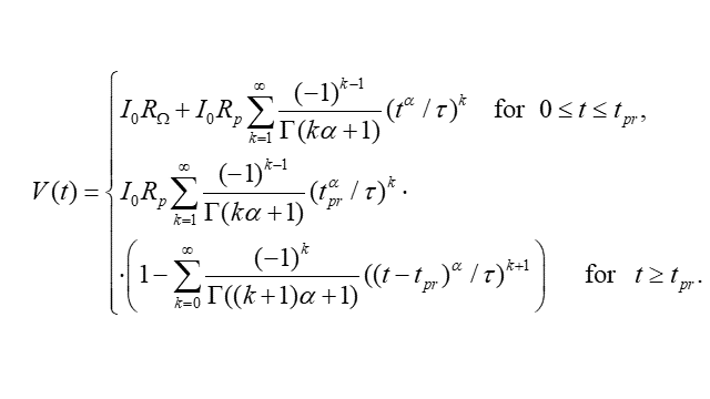
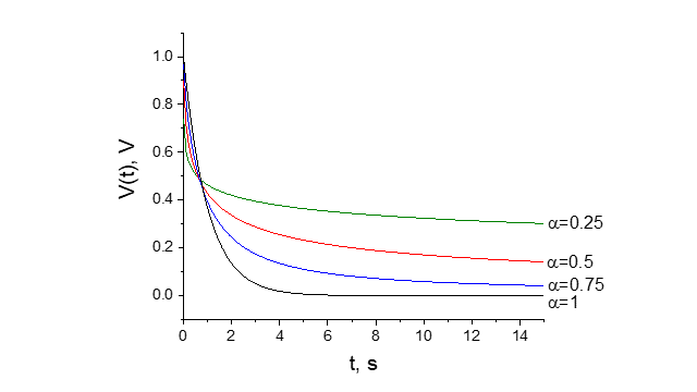
A potential response for the extended Randles circuit (Fig. 7) is given by the formula (Fig. 8). The example potential responses for various parameters α are presented in Fig. 9.
Fig. 8. Solution V(t) for the extended Randles circuit.
Fig. 9. A comparison of potential responses V(t) for parameter α={0.25,0.5,0.75,1}.
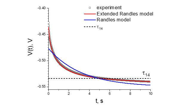
A comparison of measured and calculated potential response for the road-bridge construction at the Marywilska street in Warsaw are presented in Fig. 10. The extended Randles model describes experimental results much better in comparison to the simple Randles model.
Fig. 10. Measured (points) and calculated response in galvanostatic pulse: Randles model (blue line) and extended Randles model (red line) for the road-bridge construction at the Marywilska street in Warsaw.
In the laboratory measurements, when the surface of the rebar is known, the rate of corrosion measured by the corrosion current density can be determined from the Stern-Geary formula. In the case of large construction objects, the surface of the rebar is usually not known and consequently it is not possible to determine the corrosion rate. In this situation, a good assessment of the corrosion/passivation of the rebar in concrete can be the relaxation constant that does not depend on the surface of the rebar being tested. In the case of a corroding rod the relaxation time is short, while when the rod is in the passive state the relaxation constant is much longer.
Cooperation. Projects realized in cooperation with Road and Bridge Research Institute in Warsaw, Poland; TPS Sp. z.o.o.; Centrum Technologiczne BETOTECH Sp. z o.o.
Research papers and patents:
R. Filipek, K. Szyszkiewicz-Warzecha, J. Szczudło, Corrosion of steel in concrete – modeling of electrochemical potential measurement in 3D geometry, Arch. Metall. Mater., 65, (2020), 117–124.
R. Filipek, A. Łagosz, J. Deja, K. Szyszkiewicz-Warzecha, J. Stec, “Determination of transport and kinetic Parameters in cementitious materials – Inverse methods in corrosion of rebars in concrete”, 15th International Congress on the Chemistry of Cement Prague, Czech Republic, September 16–20, 2019.
R. Filipek, P. Pasierb, A. Królikowska, L. Komorowski, Ł. Augustyński, J. Deja, A. Łagosz, J. Migdalski, A. Lewenstam, T. Plecha, S. Kaszuba, “Nowa, nieniszcząca metoda diagnostyki procesów korozyjnych na konstrukcjach żelbetowych”, Ochrona przed Korozją, 60 (12), (2017), 391–395.
R. Filipek, K. Szyszkiewicz, “Inverse methods in corrosion research and materials degradation”, Ochrona przed Korozją, 60 (10), (2017), 358–363.
K. Szyszkiewicz, J.J. Jasielec, A. Królikowska, R. Filipek, „Determination of Chloride Diffusion Coefficient in Cement-Based Materials – A Review of Experimental and Modeling Methods: Part I – Diffusion Methods”, Cement Wapno Beton, 1, (2017), 52–67.
J.J. Jasielec, K. Szyszkiewicz, A. Królikowska, R. Filipek, „Determination of Chloride Diffusion Coefficient in Cement-Based Materials – A Review of Experimental and Modeling Methods: Part II – Migration Methods”, Cement Wapno Beton, 2, (2017), 154–167.
K. Szyszkiewicz, J.J. Jasielec, A. Królikowska, R. Filipek, „Determination of Chloride Diffusion Coefficient in Cement-Based Materials – A Review of Experimental and Modeling Methods: Part III – EIS Based Methods”, Cement Wapno Beton, 3, (2017), 219–229.
K. Szyszkiewicz-Warzecha, J. J. Jasielec, J. Fausek, R. Filipek, „ Determination of Diffusion Coefficients in Cement Based Materials: An Inverse Problem for the Nernst-Planck and Poisson Models”, Journal of Materials Engineering and Performance, 25 (8), (2016), 3291–3295.
Patent RP No. PL 231057, “Instrument for electrochemical measurements of corrosion hazard condition of engineering structures, preferably the reinforced concrete constructions and method for carrying out electrochemical measurements of corrosion hazard condition of engineering structures, preferably the reinforced concrete constructions”, Autors: Robert Filipek, P. Pasierb, A. Królikowska, L. Komorowski, patent application date 20.02.2017, date of granting the patent 31.01.2019 WUP 01/19.
Patent application No. P.420072, “Method for assessment of the probability of corrosion presence in the reinforced concrete constructions and the measuring system for the assessment of the probability of corrosion presence in the reinforced concrete constructions”, Authors: R. Filipek, P. Pasierb, A. Lewenstam, J. Migdalski, A. Królikowska, L. Komorowski, S. Kaszuba, T. Plecha, patent applicataion date: 30.12.2016.